| Role | Name | Posted from | Until |
|---|---|---|---|
| Operator | Second Subaltern Marguerite Burbage (Miss) | 1942 | 1942 |
| Operator | Second Subaltern Ann Lettice Valborg Gunter (Miss) | 1942 | 1942 |
This was the second In Station located in the Norwich area and operated from mid 1942. The first was at Rackheath Hall. This site is a Scheduled Monument. Norwich Zero-station is located on private property in Thorpe St Andrew.
Beatrice Temple visited the "new site" 10 July 1942 and 11 Aug 1942. Her visits then stop so it is assumed the Station was taken over by Royal Signals.
Report by Evelyn Simak and Adrian Pye.
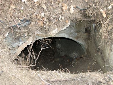
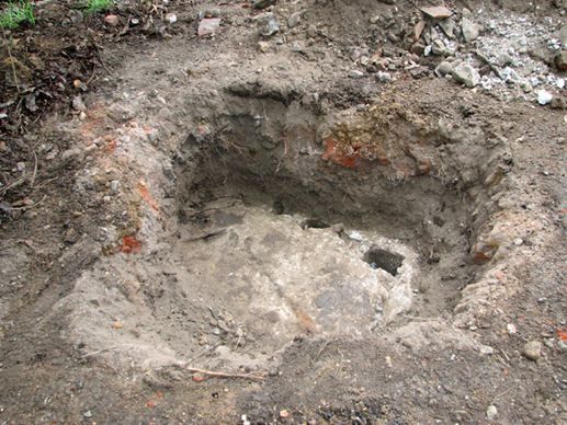
We found three concrete slabs (not original), covered by a layer of about 20 cm of soil laid over a small opening, which we established to have been the exit opening. The original cover was described to us as having been made from rough reinforced concrete which was poured onto wooden boards laid across the opening. Only concrete rubble remains.
Below the cover, a concrete culvert pipe emerges into a manhole-like space with breezeblock walls. Mention has also been made of a few steps leading down to the bottom, however, no trace remains of said steps, and no trace of steps was found during the excavation of the exit shaft. The top two rows of breezeblocks appear to have been knocked off in order to lower the shaft for better concealment when the Zero-station was closed in 1944. The top row of the breezeblocks would originally have been capped by an approximately 3 cm thick layer of concrete to stop rainwater from trickling down. The breezeblock and concrete rubble was thrown down the shaft. In the current top row of breezeblocks there are several small rectangular recesses which once would have carried a sturdy wooden frame supporting a number of pulleys.
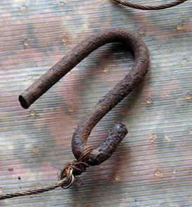
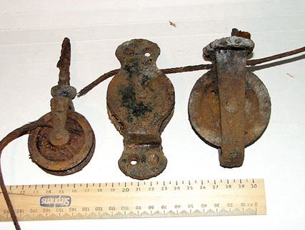
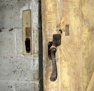
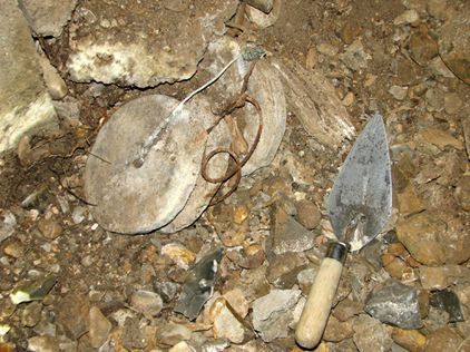
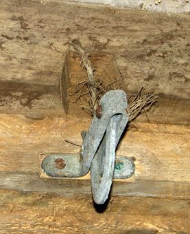
A steel hook tied to a length of twisted steel wire at the bottom of this manhole was found in 1988, along with a 0.65m long steel pipe and a C-bracket. Excavation of the exit shaft has brought to light altogether 5 small pulleys; several lengths of aerial feeder cable that appear to have been dumped here; a brass door catch (presumably for the exit hatch) and what appears to be a door handle; two shards of a glazed ceramic ventilation pipe, an ‘S’-shaped hook with a length of steel wire wrapped around it; two long (1.55m) and one short (0.65m) steel pipes, two C-brackets and numerous rusty nails.
The floor of the exit shaft is of concrete that was covered with a layer of bitumen for waterproofing. There are two rectangular openings in the floor, one containing seven cast iron sash weights of various lengths, bundled together with steel wires, acting as the counterweight of the exit hatch. Similar to a drawing found in a document believed to have come from Coleshill and dating from the 1940s, giving instructions for the building of trapdoors, the Zero-station’s exit hatch probably consisted of wooden boards or of a plywood sheet, nailed onto two lengths of 2 x 3 inch timber. The door would have been attached to the two aforementioned metal pipes - threaded through wooden battens for support and then through the boards - and fixed in place by a nut at each end. The length of these pipes indicates the original height of the drop-down shaft which would have been about 1.60m. Each one of these pipes was contained within a shorter length of (slightly wider) pipe that was affixed to a wooden frame with two C-brackets. In all probability the trapdoor mechanism would have been activated by pulling a wire. We presume that the counterweight rested on a hinged board, secured by a catch. Pulling the wire released the catch, the board dropped out from under the counterweight, and the counterweight in turn started to descend downwards until it had reached the bottom of the opening in the floor. Simultaneously, the two long pipes, held within the shorter pipe sections, were pushed upwards, resulting in the trapdoor being gradually raised horizontally above ground level. The small opening created by this action would have been just large enough to squeeze through and escape. Above ground the trapdoor would have been hidden under a layer of soil. In the event of discovery, the Zero-station would never have been used again and the emergency exit mechanism was hence intended to be used only once.
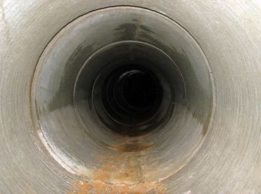
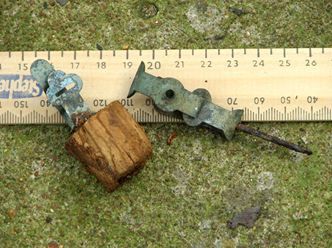
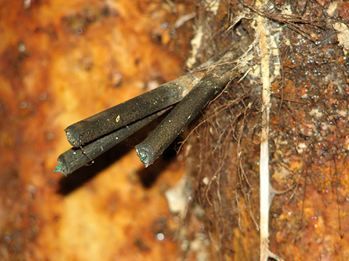
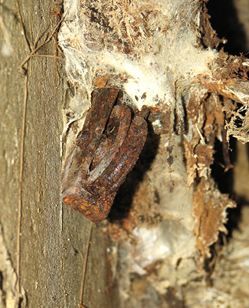
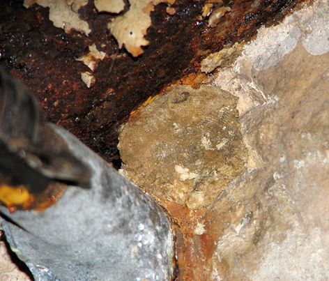
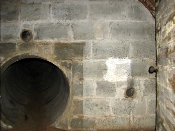
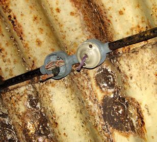
ATS personnel were not usually issued with firearms that could have been used for defending themselves, they were, however, instructed to destroy the radio sets before attempting a get-away. The escape tunnel is 17 metres long. It was constructed by aligning 18 segments of concrete culvert pipe, each measuring about 90 centimetres. The tunnel leads steadily downwards, curving in south-westerly direction about halfway down. The concrete pipes have an exterior lining of sheet metal, presumably to keep out dampness. This lining can be seen through the gaps created by the curve of the tunnel. There is evidence of the existence of two 240V power cables, running parallel to each other along the whole length of the tunnel. The cables were held in place, about half-way up the right hand side, by double cable clips, fixed in place by nails that were hammered into crude wooden plugs wedged into the gaps between two pipe sections. Some of these plugs are still in place as are a number of cable clips, some lying on the tunnel floor. The existence of at least one such cable is confirmed by Mr G who actually pulled a 6-metre length out of the tunnel. Two cables of similar type were found at Hollingbourne Zero-station in Kent but what purpose they might have served has as yet to be established.
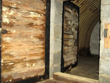
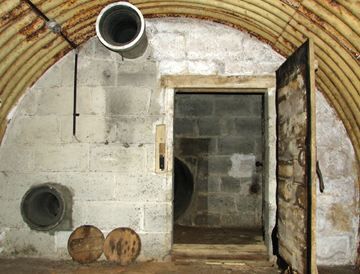
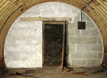
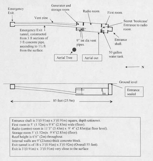
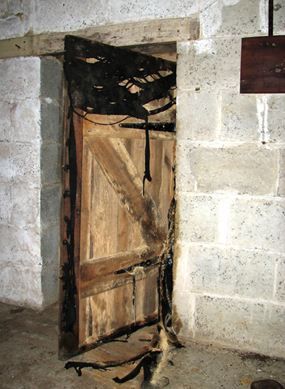
The tunnel emerges in a buried Nissen-type hut chamber (also often referred to as “elephant shelter”) consisting of three rooms which are separated by 23 cm (9 inch) thick breezeblock walls. The rooms were accessed through wooden doors which are still in place, functional and in good condition.
As the entrance opening remains sealed the only way in at present is through the emergency exit tunnel. The following description of the rooms follows the order in which they were first encountered - the last room (generator room) first and the entrance shaft last.
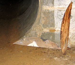
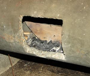
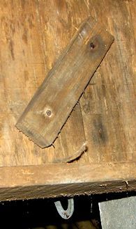
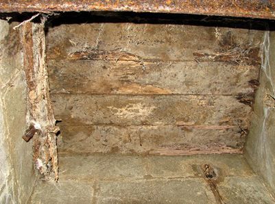
The room immediately adjoining the escape tunnel is the generator room. Looking towards the tunnel opening, evidence can be seen that the tunnel used to also be secured at this end, where it emerges into the generator room. The cover appears to have been made from wooden boards and some of the screws fixing it to the wall are still in place, embedded in the surrounding breezeblocks. Only two boards of this cover remain – both are of similar size and have one straight and one rounded edge, with the latter fitting snugly into the rounded opening of the culvert piping. One of these boards was found hidden in one of the two concrete vent pipes, the other on the floor of the ante-chamber by the entrance shaft. In all likelihood this room would have been used for housing a small generator and for storing the batteries powering the lighting as well as the TRD radio sets.
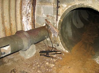
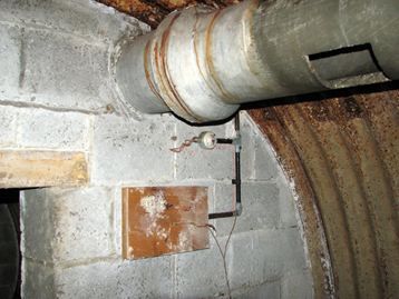
The generator would have been used for the re-charging of said batteries and for providing back-up in case of an emergency. The whitewashed wall above one of the two small glazed ceramic vent pipes in the breezeblock end wall appears to be soot-stained, indicating that it could have been used for extracting the generator’s exhaust fumes. A second, similar pipe is set into the end wall above the tunnel opening. The other end of this pipe can be glimpsed through a recess near the top of the exit shaft’s wall, indicating that at this point the pipe is actually situated within a breezeblock. The corrugated sheeting in this room was painted off-white; the floor is covered with paving stones. A fire bucket - a sand-filled fuel or food container with an improvised wooden handle - stands by the wall beside the twin doors leading into the radio room. On the left hand side (looking towards the exit tunnel) the generator room is traversed by two large concrete ventilation pipes, one near the bottom (the inlet pipe) and one near the roof (the outlet pipe). Both of these pipes have a small rectangular cut-out which provided ventilation in the generator room. The joint of the bottom pipe is supported by a piece of breezeblock.
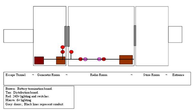
Beside the inlet pipe, right next to the tunnel opening, there is an electrical panel, albeit with all wires cut. Two approx. 60 cm lengths of power cable are still attached to it. The insulation at the ends of the two cables has been stripped and the two strands of twisted steel wire were pulled apart, in all likelihood to be clipped onto the protruding poles of the lead-acid batteries that powered the lighting as well as the radio sets. A pair of light fittings (one missing) is on the wall above. Interestingly, the course of this section of conduit as well as the position of the two light fittings can also be seen outlined on the wall in red chalk, no doubt by the Royal Engineer who installed it.
Even without much knowledge of electrics, one glance at the panels indicates that appliances other than two radio sets and presumably two lighting circuits would also have been controlled from here, but what exactly these other devices would have been remains a mystery which left our military electronics engineer friend - who had expected to find no more than 6 wires, instead of 11 - quite baffled: “Panel A (beside the entrance into the radio room) is the most complex in that it housed the light switches as well as other things. Close examination shows circular marks from what appears to have been switches. I was not expecting to see more than six wires but on this panel there are 13 – probably 5 pairs and a group of 3. I have no idea why so many. Another panel (panel B) was expected on the opposite wall but there is only a pair of wires. Panel C (in generator room) has 11 wires, again more than expected. Panel D (beside exit tunnel) is clearly the battery termination panel with a connecting block. It appeared to me that the two 6V batteries were used to power two separate circuits. This would make sense if the lights were on one and the radios on the other. The lights are clearly in pairs and it is also clear that one side of the pairs has a different type of wire and this could be because each pair consisted of one 6V 6W bulb while the other had a mains powered bulb. This is just a guess at the moment.”
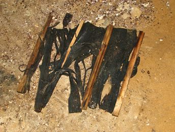
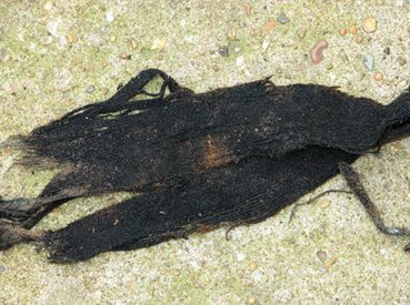
A small, simple and obviously homemade collapsible screen (measuring about 0.40 x 0.70 cm when intact), constructed from sections of oil-soaked black-out fabric (it looks like a blend of felt and Hessian) and interspersed by six or seven lengths of wood, was found lying on the floor beside the tunnel opening. It used to be attached to a piece of wood that is wedged into the small space between the outlet pipe and the roof, from where it had dropped off when the fabric holding it together deteriorated. A markedly darker area to both sides of the rectangular cut-out in said pipe indicates that this screen would have been draped around here, blocking the opening. We have so far failed to find a plausible explanation as to why this would have been necessary. A very similar set-up was found at Heiferlaw Zero-station and also at Shipley Zero-station where the cut-out was covered by what appears to have been a wooden board. A small pile of ash that appears to have originated from burnt paper can be seen through the rectangular cut-out in the inlet pipe – perhaps the remains of code sheets that were burnt when the Zero-station was closed?
The radio room is separated from the generator room by twin doors - two sturdy wooden doors with a raised threshold in-between. The doors are intact, fully functional and complete, including hinges, handles and catches. It is interesting to note, however, that the Norfolk-barn-door type catch was replaced by a much stronger one on the inner door. Both doors have a thick black textile fabric affixed all the way around their outer rims, albeit only on the sides that face each other when both are closed. We believe that this fabric, which appears to have been soaked in oil, served several purposes, depending on where it was used: to stop light penetrating through (entrance door); for protection from poison gas; for sealing the twin doors in order to prevent generator exhaust fumes from penetrating into the radio room (twin doors at exit); and for sealing the cut-out in the outlet pipe (in generator room) for reasons not yet fully understood.
There are two thumb-sized holes at one end of the door lintel and there is also cable clip just below, which indicates that two cables were fed through these holes. What type of cables they were and purpose they might have served we do no know. On the whitewashed wall beside it, three straight vertical lines can be seen drawn with a pencil at equal distances, and there are also three wooden plugs in the cement seam between two rows of breezeblocks - indicating that a small shelf was once affixed here. If so, no trace of it remains. The two aforementioned concrete ventilation pipes, the inlet and the outlet pipe (traversing the generator room) emerge in the radio room, to the left of the twin doors (viewed from the entrance doorway). Their homemade wooden plugs (in all probability used for noise and generator exhaust fume reduction) are in situ.
In the radio room the cable conduit runs all the way along the roof, terminating at what we believe was the main panel or switchboard on the opposite wall, beside the entrance doorway. Once again, the set-up of the wiring is confusing and all the switches were removed. The floor of the radio room is covered with precisely laid concrete paving slabs which in turn were covered by a layer of brown linoleum, small sections of which are still in place - some bearing the indents of objects that once stood on them. The breezeblock end walls are whitewashed and the corrugated sheeting is painted off-white.
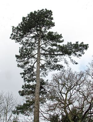
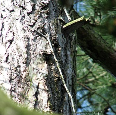
Three aerial feeder cables disappear through the wall at about 40 cm above floor level near the right-hand corner (near the entrance doorway). The presence of three feeder cables indicates that there were three aerials – with possibly, but not necessarily each one running up a separate tree. The table for the radio sets would have stood near this corner in the vicinity of the aerial feeder cables and the main switchboard.
Above ground, part of one of the aerial feeder cables can still be seen high up on a pine tree, situated about 5 to 10 metres from where the duct enters the radio room through the west wall. The tree (Pinus silvestris) has the conservation number 0723 and cannot be felled. The length of feeder cable will therefore be safe for as long as it takes for the wind to take it down.
Back inside the radio room: the presence of different types of wires (orange at left, mauve at right) indicates that there would have been two lighting circuits - one AC circuit probably at 250V, derived from the Chorehorse generator or similar, and another, totally separate circuit for silent, battery-powered running at 6V just as the radios did. Two pairs of light fittings are in the radio room (on ceiling) and a similar pair is in the generator room (on wall). Remains of tiny 6V 6W “Sunshine” light bulbs with bayonet fittings were found lying on the floor in a corner. From this we can safely assume that the lighting conditions would have been very poor indeed.
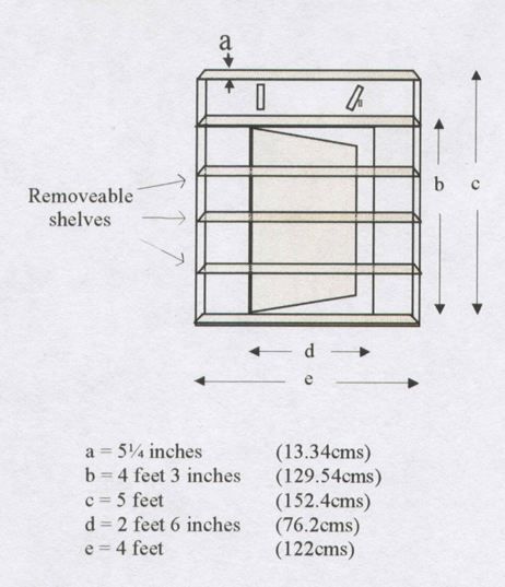
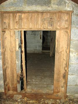
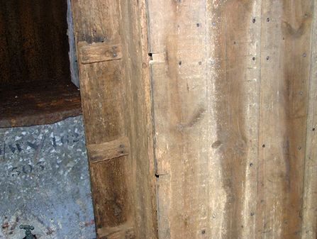
We had read about the existence in Zero-stations of a hidden door leading from the ante-chamber by the entrance into the radio room, and also that for anybody not in the know the ante-chamber would have had the appearance of a small storage room, giving no clue as to what lay hidden behind the wall. At Norwich Zero-station, the interior (radio room) side of this door is covered entirely with the already mentioned sticky black textile fabric, large sections of which are still in place, albeit in shreds. The other side of this door, however, appears to be something different entirely. Coming down the entrance shaft, the uninitiated would have found themselves in a small room that to all intents and purposes was used for storage, with a small water tank standing against the wall on one side. On the wall facing the entrance shaft they would have seen a storage shelf, stacked with boxes and tins and perhaps a few boxes of ammunition. This shelf is designed to look like a bookcase, with a frame extending to both sides of the doorframe (overlapping it) and also to above the door up to a height of 1.65m. The wooden brackets which would have supported the removable shelves are still in place and the door itself has small cut-outs so that the shelves fitted partially into it, perfectly concealing both the door and the door frame when the shelves were in place and the door closed. The shelf boards are missing but the bookcase-style frame is in situ – and it is the one only known to be still in existence. The section extending to above the door lintel has two lengths of wood affixed to the panels covering the wall. These lengths of wood, one on each side, appear to be fixed in place by two screws, one at each end. The one on the right hand side, however, is held by only the top screw. The bottom ‘screw’ is actually a nail. This piece can be moved sideways and in doing so it reveals a small carved out recess and a hole drilled through it. The hole is just large enough to allow for a piece of string to pass through. The other end of this string is still tied to the door catch (on the radio room side), which could be released by pulling said string, and the radio room could then be entered by swinging forwards the door - but not without first removing at least some of the shelves. Standing in the door, the last person to enter the radio room would have replaced the shelves and the items stored on them. On closing the door it would once again have been invisible to anyone from outside.
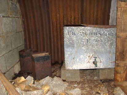
The ante-chamber by the entrance shaft still houses a 50-gallon water tank, covered with a piece of sheet metal. The tank is still ¾ full of water and rests on four concrete plinths. Beside it there are two fire buckets, old fuel or food containers with improvised wooden handles, filled with sand.
The walls of the entrance shaft, the breezeblock end wall of the ante-chamber and the corrugated sheeting in this room were not painted. The floor is covered with concrete paving slabs. The room does not contain any other items, but a chemical toilet (Elsan) would in all likelihood once have stood by the wall opposite the water tank, hidden behind a curtain.
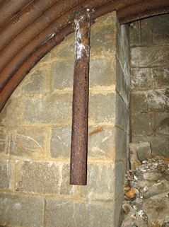
The drop down entrance-shaft faces the secret doorway into the radio room. A wooden or steel ladder would once have been used for access. A large heap of concrete rubble is lying at the shaft’s floor. Presumably this rubble was created when the top of the shaft was lowered by removing the top layers of breezeblocks, in order to hide its presence when the opening was sealed up after stand-down. Affixed to the wall to the left of the entrance shaft (seen from the radio room) there is a cast iron pipe which ends at about 50 cm above floor level. Civilian informants might have used it to drop off their messages here, concealed in split tennis balls, to be read and then forwarded to headquarters by ATS personnel.
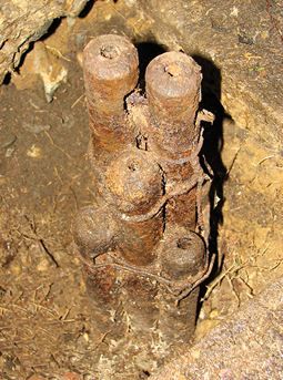
Other sources have suggested that the pipe was used for ventilation purposes, and indeed the pipe would have been the only source of ventilation in the ante-chamber. It is possible that it served both purposes. A number of lead counterweights (16 cm diameter, 2 cm high approximately), each with a hexagonal opening at its centre and still held together by a length of twisted wire, were found buried under the rubble at the bottom of the entrance shaft. As both the size and the quantity of the counterweights would have been defined by the finished weight of the trapdoor, the weights in all likelihood would have been made on site: a roughly saucer-shaped scoop would have been made in the sand and a bolt stood upright in its centre before molten lead was poured into the depression. When set, the bolt was knocked out and the process repeated until there were enough weights to counter-balance the trapdoor. The weights would once have been attached to the pulley system that was used for operating the opening mechanism of the entrance hatch.
Viewed from below, the entrance opening is covered over with wooden boards. Almost at the current top of the breezeblock wall there are several small rectangular recesses. They held the wooden frame that surrounded the opening and probably supported the entrance hatch. A small pulley still adheres to a section of badly deteriorated wooden frame (it has since come down). Two more pulleys were found amongst the rubble below. The pulleys formed part of the opening mechanism that operated the concealed hatch. Remains of sticky black, oiled fabric are still adhering to the wall above the roofline of the corrugated iron shelter.
Finding the exact location of the entrance from above ground was difficult and it took some plotting and planning as well as shouting and banging on the roof before the exact spot could be found and excavated. The entrance was sealed by laying wooden boards across the opening and then pouring rough concrete, reinforced by lengths of (probably waste) metal rods and what appears to be a section of gas pipe, on top of it. The concrete cap is covered by an approximately 40 cm thick layer of soil.
Dimensions: Overall length from entrance to exit incl tunnel: 85ft = 26 metres Thickness of end walls: 23 cm/ 9in. Material: breezeblocks Roof height: 2.10m (6ft 10 inches) Entrance shaft: 0.90 x 0.90m / 3 x 3ft – 2.80 m (9ft) high from floor to covering boards Dimensions of ante-chamber room: 1.50 x 2.85m (5 ft x 9ft 4inches) on floor. Paving stones on floor. Walls unpainted Water tank: 0.76 wide x 0,55 x 0.55m - ¾ quarters full of water – sheet metal cover– tap in working order Concealed door: 1.35 x 0.81m – doorstep 4 cm high. Back blacked-out Bookcase-shelf: 17 (outer frame) x 24 x 14 (inner frame) cm deep Shelf: 14 cm deep x 1.24 m long, 3 cm thick board. Height: 1.65m Dimensions of piece of wood that conceals door catch mechanism: 22.5 x 5 x 3 cm Radio room: 3.50 x 2.85m (11ft 3inches x 9ft 4inches) measurements taken on floor Large inlet/outlet pipes: concrete; both 23 cm (9 in) internal diameter Floor in radio room: Paving stones, covered with linoleum. Breezeblock end walls whitewashed, corrugated steel wall off-white Exit doorways: 1.50 x 0.93 m – doorstep 78 cm wide by 11 cm high. Black-out fabric around inner edges Generator room: 1.50 x 2.85m (5ft x 9ft 4inches) measurements taken on floor. Paving stones on floor, walls painted 2 small glazed ceramic vent pipes, one above tunnel (10 cm), one opposite twin doors (8 cm) - wall above soot-stained Exit tunnel: 18 3-foot sections of concrete pipe, 55 ft long = not quite 17 metres with exterior lining of sheet metal Exit opening: 1.20 (H) x 0.95 (W) x 0.70. 1 openings in concrete floor: 28 x 34 cm; 21 x 24 cm for counterweights Exit hatch mechanism: 2 steel pipes 1.55m long; 2 nuts each at threaded end, spaced 7 cm apart; wooden plug in other end; 2 cm internal diameter; 1 steel pipe 0.65m long, 3.5cm internal diameter (its twin plus one C bracket is kept by Mr G) 5 pulleys 2 C-brackets (a third kept by Mr G) Counterweight at exit (a bundle of 7 sash weights) – weight 25 kg (55 lbs) Counterweight at entrance (4 lead weights tied together) – weight 13.6 kg (30 lbs)
Thorpe St Andrew Instation
Arthur Gabbitas
Evelyn Simak & Adrian Pye
David Lampe (The Last Ditch); John Warwicker (With Britain in Mortal Danger; Churchill’s Underground Army); Frank Hewitt (pers comm.); Brian and Bob from Surrey;